This tutorial walks through deploying a Powerlynx hotspot on a MikroTik device that also acts as a CAPsMAN controller for one or more MikroTik APs. Wireless clients associate to the APs, but all captive-portal redirection, RADIUS authentication and accounting happen on the central controller — fed from Powerlynx.
The example uses a hAP ac lite as the controller and two CAPs (a MikroTik AC3 and AX2) on RouterOS 7.21+, but any combination works as long as the controller runs ROS 7.13+.
Warning: Some parameters in this guide must be tailored to your environment — country code, SSID names, security passphrases, channel widths, AP-facing Ethernet ports, etc. Wireless deployments are highly site-specific; copy the structure, not the literal values.
1. Overview
Powerlynx provides AAA (authentication, authorisation, accounting) and the captive splash page; MikroTik handles the user data plane. CAPsMAN lets one MikroTik device push a unified wireless configuration to several APs, so you configure the wifi once and add APs as you grow.
A single CAPsMAN controller can manage one or many MikroTik AP devices running:
- the unified
wifipackage (ROS 7.13+, formerlywifi-qcom/wifi-qcom-ac), or - the legacy
wirelesspackage on older AP firmware — same idea, configured under/caps-maninstead of/interface/wifi.
2. Topology & Roles
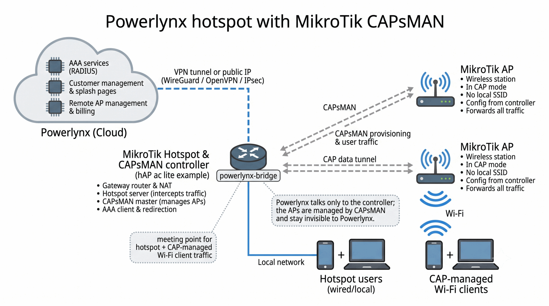
- AP (AC3, AX2) — acts as a wireless station for end users, forwarding all traffic to the hotspot controller. Runs in CAP mode; no local SSID/security/channel config — it receives everything from the controller.
- Hotspot Controller — directly connected to Powerlynx (over a VPN tunnel) and to the hotspot network devices. Responsible for redirecting client traffic to Powerlynx (captive portal, RADIUS), and for CAPsMAN provisioning of the APs.
- Powerlynx — provides AAA services and instructs the hotspot controller on who is allowed to connect, and when to connect/disconnect each user.
The meeting point on the controller is powerlynx-bridge. Traffic from CAP-managed wifi clients lands on this bridge, and the Powerlynx hotspot server intercepts on the same bridge — that’s the integration.
The VPN tunnel between the controller and Powerlynx is just a secure transport. See section 8 for the supported transport options.
3. Prerequisites
- A MikroTik device for the controller role (any model, RouterOS 7.13 or newer).
- One or more AP devices. They will be configured as CAPs; their existing wifi config will be replaced by what the controller pushes.
- A wired Ethernet uplink from each AP to the controller (directly or via a switch).
- A Powerlynx account and a location created in the Powerlynx admin.
4. Step 1 — Generate and run the Powerlynx Simple Setup script
Follow the official Powerlynx documentation: https://docs.powerlynx.app/networking/mikrotik.html#simple-setup.
After the script runs on the controller, verify it produced the expected objects:
/interface/bridge/print where name=powerlynx-bridge
/ip/hotspot/print
/radius/print
/ip/hotspot/walled-garden/print
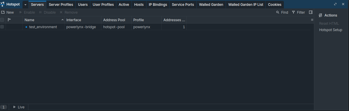
Note: At this point the hotspot is functional for any device plugged into a port that is a member of
powerlynx-bridge. The remaining steps add wireless access via CAPsMAN-managed APs.
5. Step 2 — Configure CAPsMAN on the controller
All commands below are on the controller, under /interface/wifi. Set the values to match your environment (country, SSIDs, security passphrases). Passphrases are intentionally not included in this guide — set your own.
5.1 Security profiles
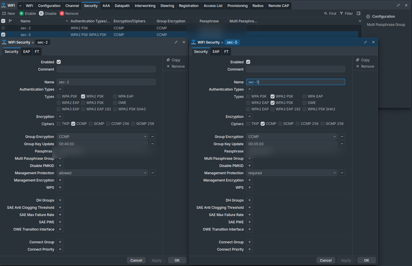
Two profiles — one tuned for 2 GHz (WPA2 only, since not every device supports WPA3 on 2.4 GHz), and one stricter for 5 GHz (WPA2 + WPA3, management protection required):
/interface/wifi/security
add name=sec-2 authentication-types=wpa2-psk encryption=ccmp \
    group-encryption=ccmp group-key-update=40m \
    management-protection=allowed ft=yes ft-over-ds=yes
add name=sec-5 authentication-types=wpa2-psk,wpa3-psk encryption=ccmp \
    group-encryption=ccmp group-key-update=5m \
    management-protection=required ft=yes ft-over-ds=yes
Then set passphrases interactively (not stored in this guide):
/interface/wifi/security set [find name=sec-2] passphrase="<your 2GHz PSK>"
/interface/wifi/security set [find name=sec-5] passphrase="<your 5GHz PSK>"
5.2 Channels
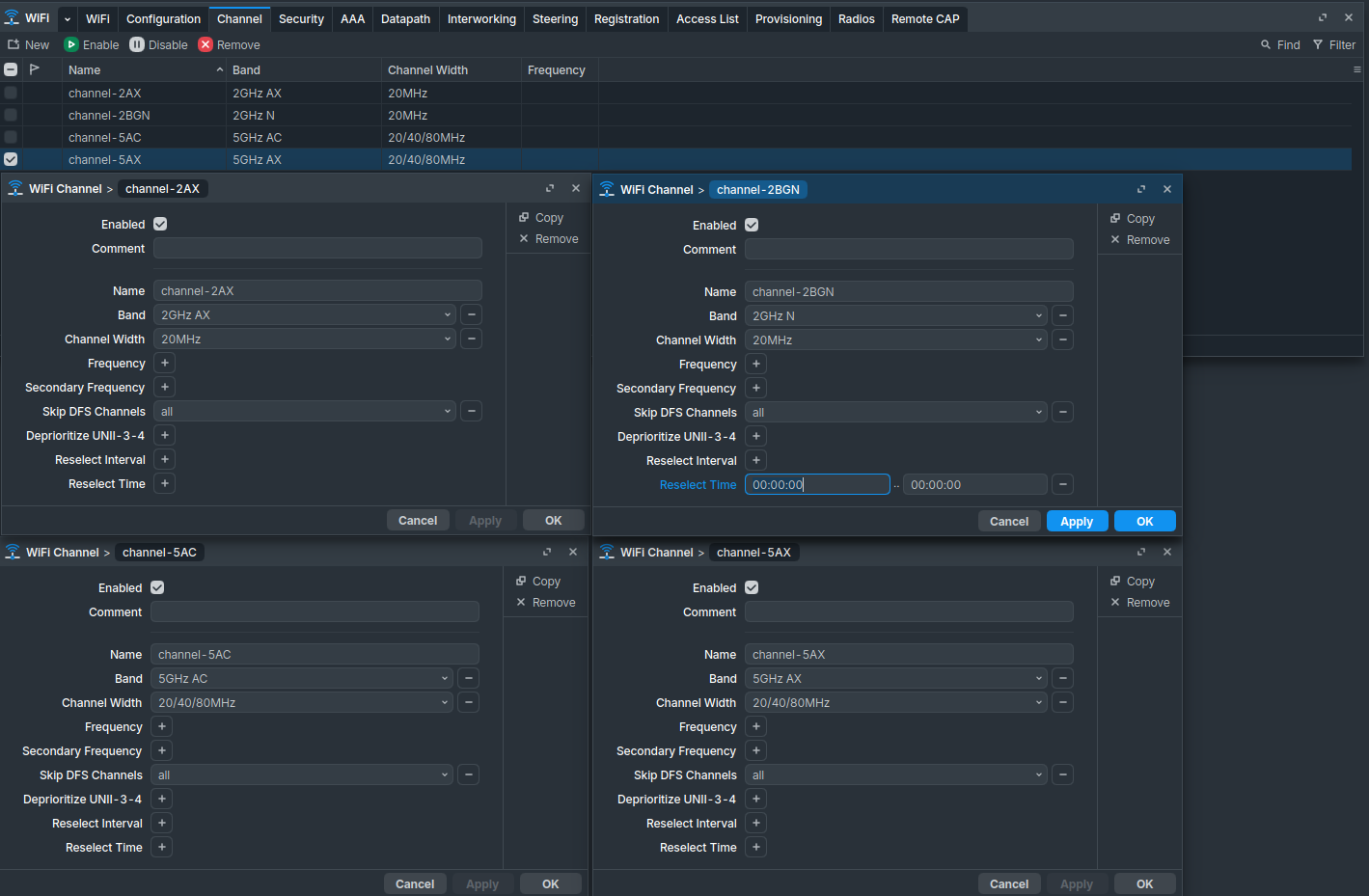
Four channels, one per band/standard:
/interface/wifi/channel
add name=channel-2BGN band=2ghz-n  width=20mhz       skip-dfs-channels=all
add name=channel-2AX  band=2ghz-ax width=20mhz       skip-dfs-channels=all
add name=channel-5AC  band=5ghz-ac width=20/40/80mhz skip-dfs-channels=all
add name=channel-5AX  band=5ghz-ax width=20/40/80mhz skip-dfs-channels=all
skip-dfs-channels=allis shown here for the lab / test deployment so the radio comes up immediately without waiting for radar clearance. Do not use this setting in production — it permanently bars the AP from the DFS portion of the 5 GHz band and significantly reduces the usable channel pool, increasing co-channel interference. In production, omit the parameter (or useskip-dfs-channels=10min-cac) so DFS channels are available.
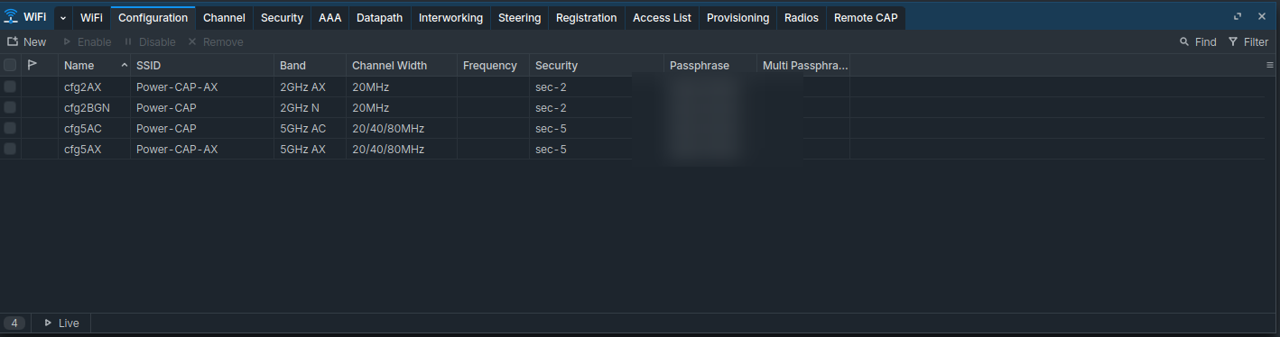
5.3 Configurations
A configuration ties a band, a channel, a security profile, an SSID and the radio mode together. The example uses two SSID names — Power-CAP (for AC radios) and Power-CAP-AX (for AX radios) — replace with your own. Set country= to your country.
/interface/wifi/configuration
add name=cfg2BGN mode=ap country=<your country> ssid="Power-CAP"    \
    security=sec-2 channel=channel-2BGN multicast-enhance=enabled
add name=cfg2AX  mode=ap country=<your country> ssid="Power-CAP-AX" \
    security=sec-2 channel=channel-2AX  multicast-enhance=enabled
add name=cfg5AC  mode=ap country=<your country> ssid="Power-CAP"    \
    security=sec-5 channel=channel-5AC  multicast-enhance=enabled
add name=cfg5AX  mode=ap country=<your country> ssid="Power-CAP-AX" \
    security=sec-5 channel=channel-5AX  multicast-enhance=enabled
5.4 Enable CAPsMAN
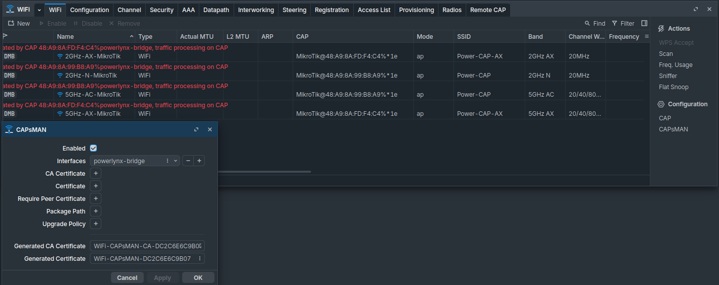
Turn on the controller role and bind it to powerlynx-bridge — this is the bridge the captive portal lives on, so it must also be where CAP traffic arrives:
/interface/wifi/capsman set enabled=yes interfaces=powerlynx-bridge
5.5 Provisioning
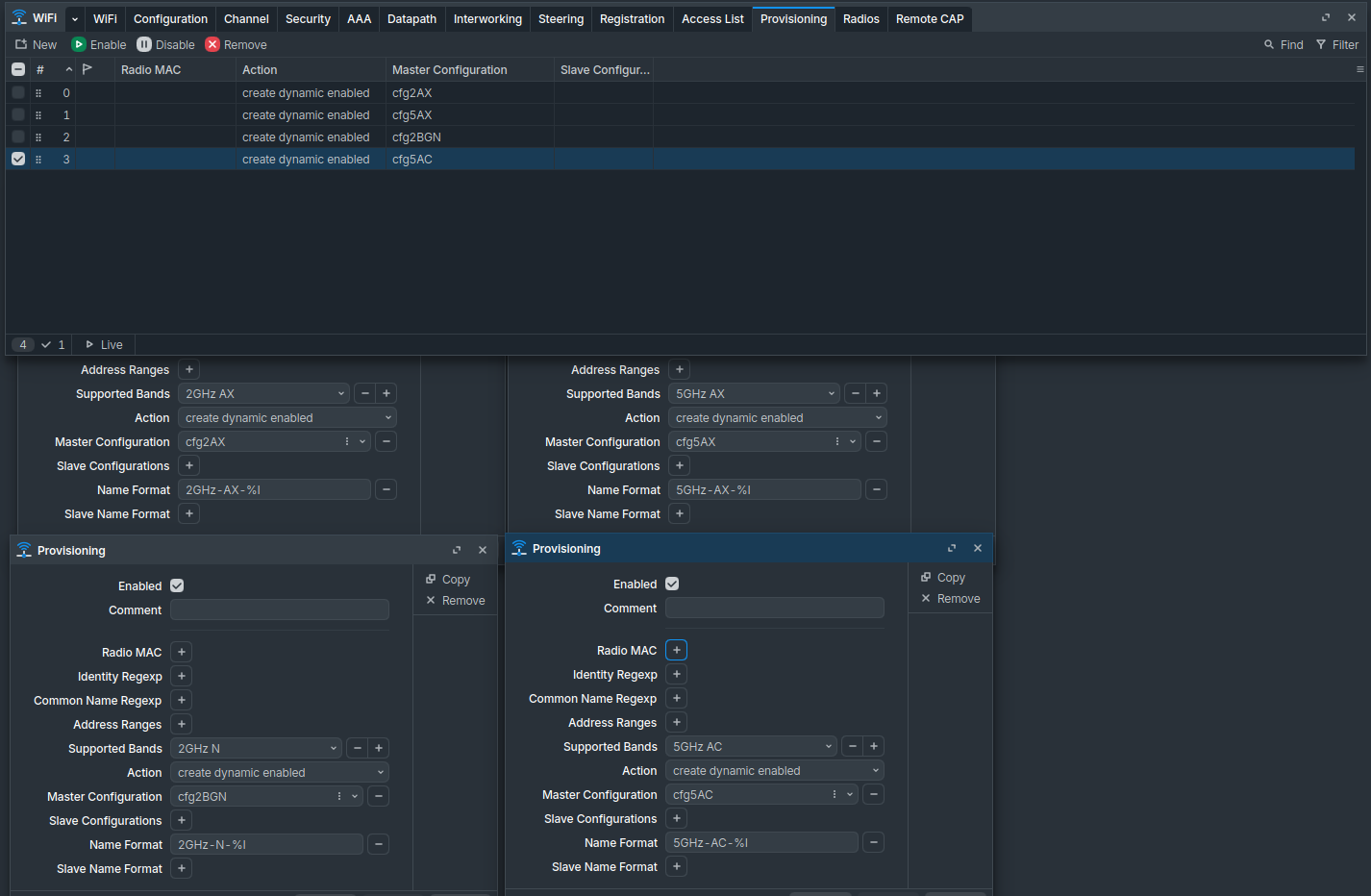
Provisioning rules tell CAPsMAN what to push to a CAP when it registers. One rule per configuration; action=create-dynamic-enabled auto-creates the virtual interface on the AP when it joins:
/interface/wifi/provisioning
add action=create-dynamic-enabled master-configuration=cfg2BGN
add action=create-dynamic-enabled master-configuration=cfg2AX
add action=create-dynamic-enabled master-configuration=cfg5AC
add action=create-dynamic-enabled master-configuration=cfg5AX
Tip: A rule with no
radio-macfilter applies to all APs. To pin a configuration to a specific AP, setradio-mac=<AP wifi MAC>on the rule.
6. Step 3 — Enable CAP mode on each AP device
Each AP needs (a) a wired uplink reachable on the same L2 as the controller, and (b) CAP enabled. On the AP (not the controller):
/interface/wifi/cap
set enabled=yes \
    discovery-interfaces=<uplink interface, e.g. ether1> \
    bridge=none
capsmandefault) puts the AP into CAP mode automatically and you can skip the manual/interface/wifi/capcommands above. Same applies to routers used in the AP role.
Important:
discovery-interfacesis the AP-side port the CAP uses to look for a controller.bridge=noneis correct when the controller manages the data plane — the AP forwards client traffic to the controller as MAC-tagged CAPWAP frames.
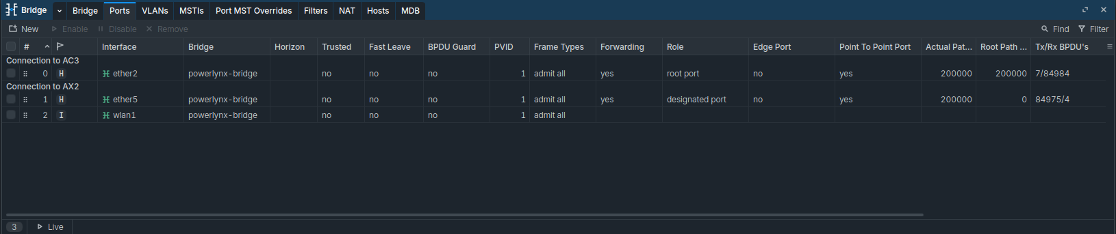
On the controller, make sure the port that physically connects to each AP is a member of powerlynx-bridge:
/interface/bridge/port
add interface=ether2 bridge=powerlynx-bridge comment="Connection to AC3"
add interface=ether5 bridge=powerlynx-bridge comment="Connection to AX2"
7. Verification
On the controller:
/interface/wifi/print
You should see the four dynamic interfaces created by provisioning, each with MDB flags and a ;;; operated by CAP <mac>%powerlynx-bridge note — confirming both the AP registration and the bridge binding.

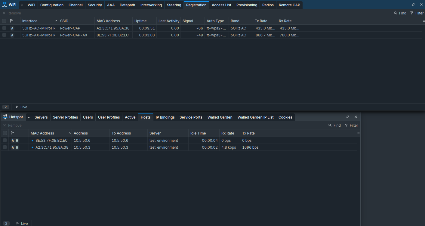
Then check the registration and hotspot host tables:
/interface/wifi/registration-table/print
/ip/hotspot/host/print
A successfully connected wireless client should appear in both tables — first associated to a CAP radio, then leasing an address from hotspot-pool and showing under the test_environment server.
8. Notes & Variations
- Multiple APs of the same model. Provisioning rules with no
radio-macfilter apply to every AP, so plugging in a third or fourth identical AP requires no extra config — it auto-provisions. - Different SSIDs per AP. Add a second set of configurations (
cfgA-2,cfgA-5, …) and bind them to specific APs withradio-mac=…in the provisioning rule. - Legacy
wirelesspackage APs. On older AP firmware, configure the same idea under/caps-manon the controller (security-profiles, channels, datapaths, configurations, provisioning). The datapath must referencepowerlynx-bridgeas its bridge. - VPN type. Powerlynx supports WireGuard, OpenVPN and IPsec as transport options for the controller-to-cloud tunnel. Alternatively, if the controller has a reachable public IP address, the tunnel can be omitted and Powerlynx talks to the controller directly over that public IP.
- Mixed deployment. A controller running both local wifi (its own onboard radio via
/interface/wireless) and CAPsMAN is fine, as long as the local wifi interface is also bridged intopowerlynx-bridge.
9. Reference summary
| Component | Value |
|---|---|
| Controller bridge | powerlynx-bridge (10.5.50.1/24) |
| Hotspot pool | hotspot-pool (10.5.50.2–10.5.50.254) |
| Hotspot profile | powerlynx |
| Hotspot server | named after your Powerlynx location |
| RADIUS target | Powerlynx VPN endpoint (via tunnel) |
| Walled garden | *.powerlynx.app |
| CAPsMAN interfaces | powerlynx-bridge |
| Security profiles (example) | sec-2 (WPA2), sec-5 (WPA2+WPA3) |
| Configurations (example) | cfg2BGN, cfg2AX, cfg5AC, cfg5AX |
| Provisioning | create-dynamic-enabled per configuration |
| AP role | /interface/wifi/cap enabled=yes |