Hybrid Network Configuration: Simultaneous Splynx PPPoE & Powerlynx Hotspot
This guide details the implementation of a network topology where a MikroTik NAS serves both standard ISP subscribers via PPPoE (managed by Splynx) and temporary/guest access via a Hotspot (managed by Powerlynx) on the same physical link.
Use Case: A CPE device normally connects via PPPoE for permanent internet access. However, specific interfaces (e.g., a Guest WiFi SSID) or the device itself during a PPPoE outage can redirect traffic to a Powerlynx Captive Portal via a dedicated VLAN.
Warning: Not all vendors support such network configuration, so be cautious with the device’s choice. We recommend discussing it with your dedicated network engineers.
Network Topology & Roles
…
Note: This setup acts as a baseline example. It can be improved and adapted to your specific network topology as you wish. You are encouraged to implement your own network configuration or enhance this one by adding other L2/L3 devices to the topology.
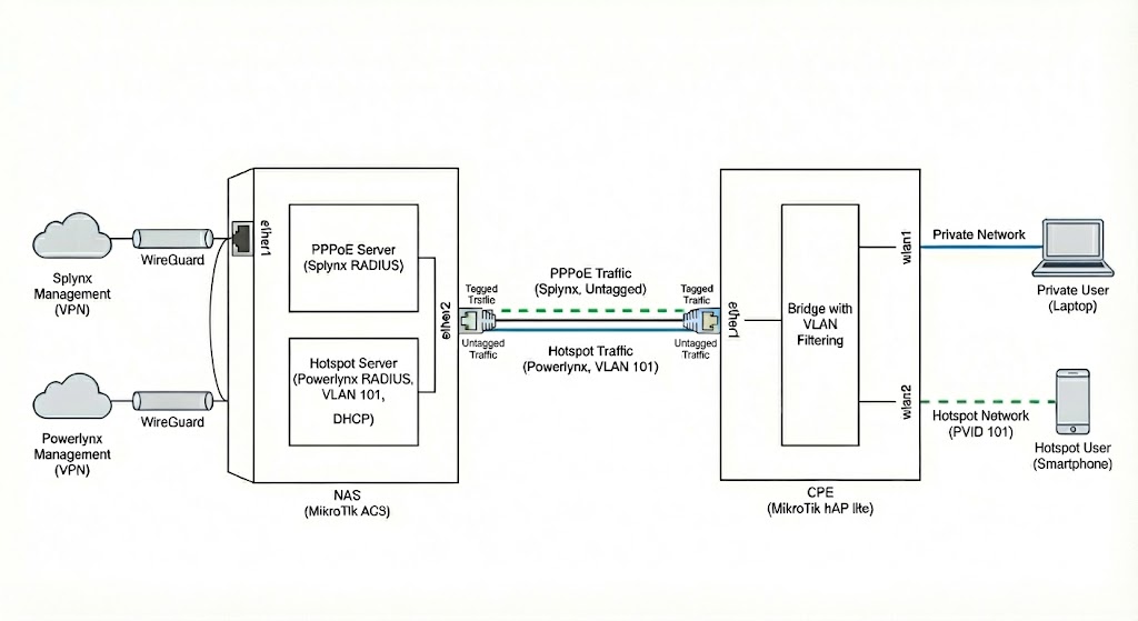
NAS Device (MikroTik AC3)
Acts as the Service Gateway.
-
Services: PPPoE Server (Splynx RADIUS), Hotspot Server (Powerlynx RADIUS), DHCP Server.
-
Uplink: WireGuard tunnels to management platforms.
-
Downlink: ether2 connects to the CPE.
CPE Device (MikroTik hap lite)
Acts as the Client Gateway.
-
Uplink: ether1 connects to the NAS.
-
Services: PPPoE Client (for primary internet), L2 Bridge with VLAN filtering (for Hotspot redirection).
Warning: This configuration relies on Bridge VLAN Filtering. Ensure your MikroTik hardware switch chip supports this feature efficiently to avoid CPU bottlenecks.
Part 1: MikroTik NAS Configuration (AC3)
The NAS is configured to handle two distinct traffic flows on the same physical interface (ether2): untagged traffic for PPPoE discovery and tagged traffic (VLAN 101) for Hotspot access.
1. Management & Connectivity
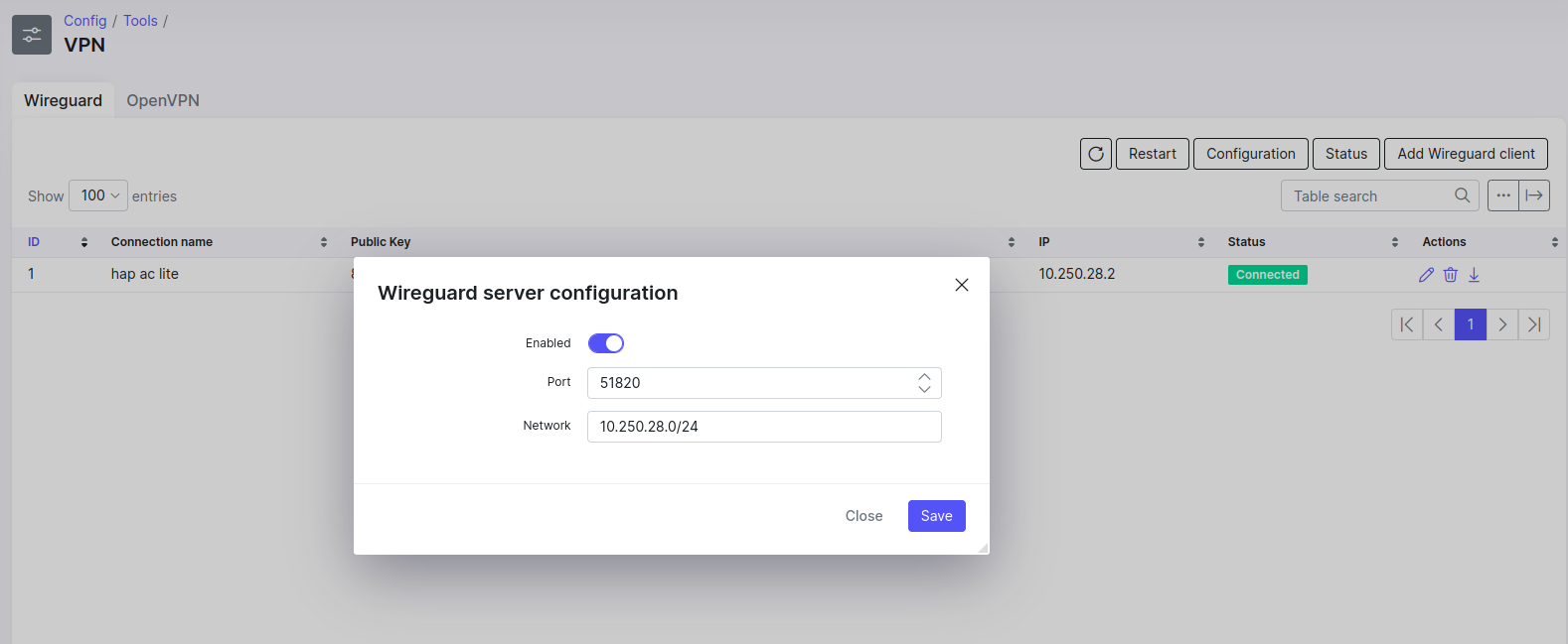
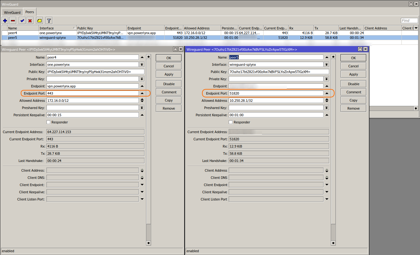
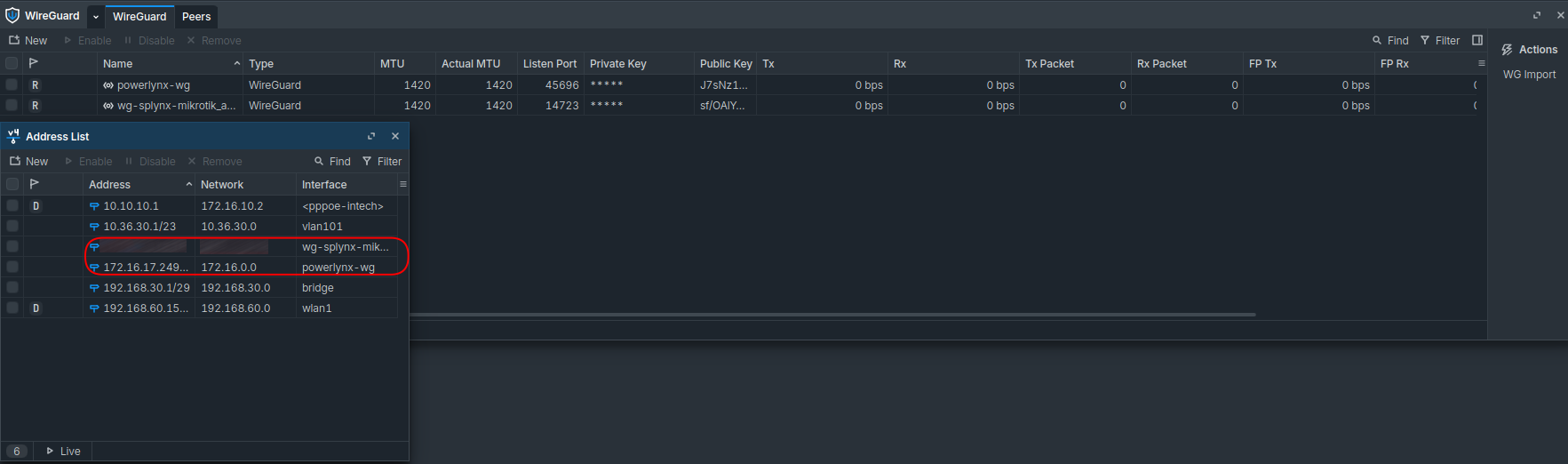
Establish WireGuard tunnels for Splynx and Powerlynx communication.
Code example:
/interface wireguard

add listen-port=45696 mtu=1420 name=powerlynx-wg

add listen-port=14723 mtu=1420 name=wg-splynx-mikrotik_ac3

/interface wireguard peers

# Powerlynx Peer

add allowed-address=172.16.0.1/12 endpoint-address=vpn.powerlynx.app \

endpoint-port=443 interface=powerlynx-wg name=peer2 persistent-keepalive=15s \

public-key="POWERLYNX_PUB_KEY"

# Splynx Peer

add allowed-address=1.1.1.1/32 endpoint-address=splynx_wireguard_server \

endpoint-port=51820 interface=wg-splynx-mikrotik_ac3 name=peer3 \

persistent-keepalive=1m public-key="YOUR_SPLYNX_PUB_KEY"

/ip address

add address=172.16.17.249/12 interface=powerlynx-wg network=172.16.0.0

add address=YOUR_WG_IP interface=wg-splynx-mikrotik_ac3 network=YOUR_SPLYNX_WG_NETWORK
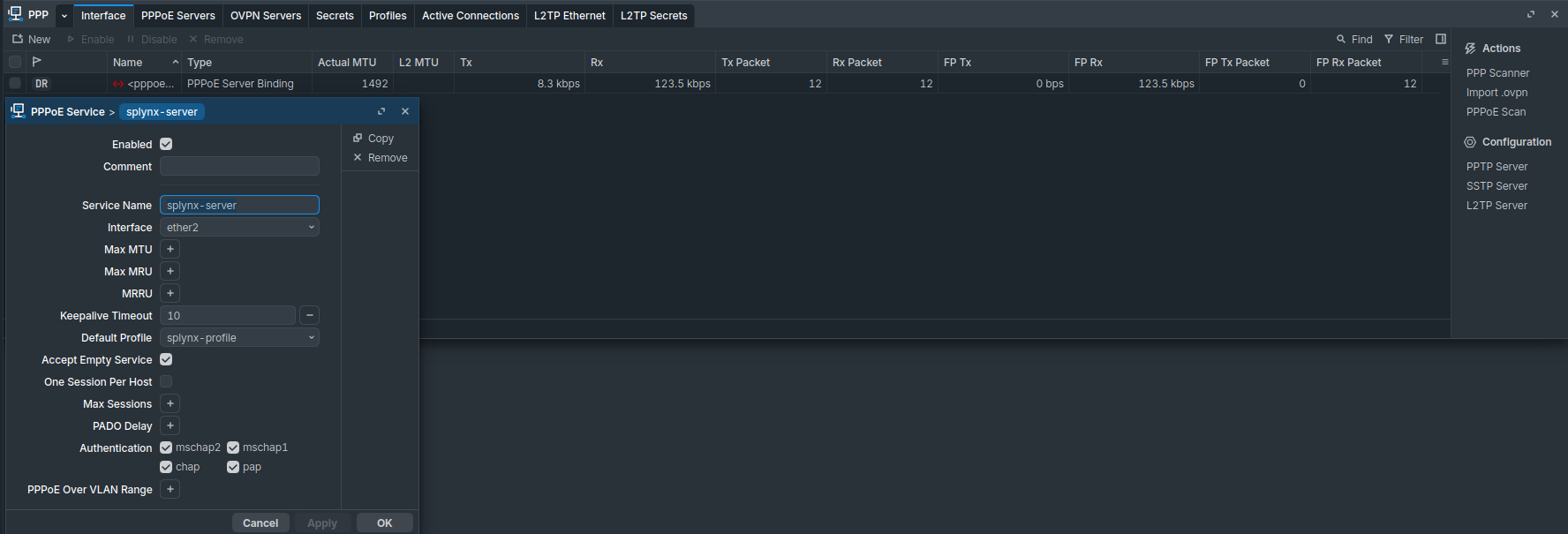
2. Splynx (PPPoE) Configuration
This configuration sets up the PPPoE server on ether2. It utilizes Splynx for AAA (Authentication, Authorization, Accounting).
Code example:
/ppp profile
add change-tcp-mss=yes local-address=10.10.10.1 name=splynx-profile use-ipv6=no
/interface pppoe-server server
add default-profile=splynx-profile disabled=no interface=ether2 service-name=splynx-server
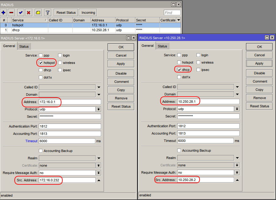
/radius
add address=SPLYNX_WG_IP comment="Splynx Radius" require-message-auth=no \
service=ppp src-address=YOUR_WG_IP timeout=3s
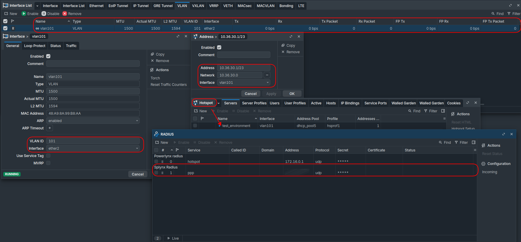
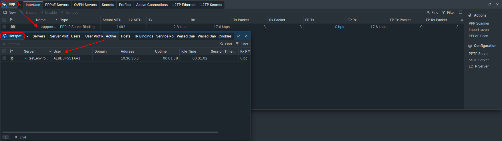
3. Powerlynx (Hotspot) Configuration
The Hotspot is isolated inside VLAN 101. The NAS listens for tagged frames on ether2.
Code example:
# VLAN Interface for Hotspot

/interface vlan

add interface=ether2 name=vlan101 vlan-id=101

# IP Addressing & DHCP

/ip address

add address=10.36.30.1/23 interface=vlan101 network=10.36.30.0

/ip pool

add name=dhcp_pool5 ranges=10.36.30.2-10.36.31.254

/ip dhcp-server

add address-pool=dhcp_pool5 interface=vlan101 name=dhcp2

/ip dhcp-server network

add address=10.36.30.0/23 dns-server=8.8.8.8,1.1.1.1 gateway=10.36.30.1

# Hotspot Setup

/ip hotspot profile

add dns-name=local.hotspot hotspot-address=10.36.30.1 login-by=mac,http-chap \

mac-auth-mode=mac-as-username-and-password name=hsprof1 nas-port-type=ethernet \

use-radius=yes

/ip hotspot

add address-pool=dhcp_pool5 addresses-per-mac=1 disabled=no idle-timeout=2m \

interface=vlan101 keepalive-timeout=30m name=test_environment profile=hsprof1

# RADIUS for Powerlynx

/radius

add address=172.16.0.1 comment="Powerlynx Radius" require-message-auth=no \

service=hotspot src-address=172.16.17.249 timeout=6s

# Walled Garden (Allow access to splash page assets)

/ip hotspot walled-garden

add dst-host=*.digitaloceanspaces.com

add dst-host=your_powerlynx_domain
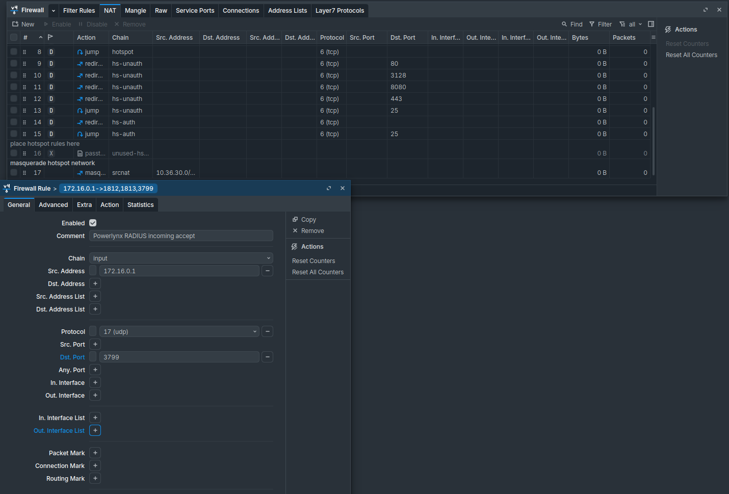
4. Firewall & NAT
Ensure RADIUS traffic is permitted and customer traffic is masqueraded.
Code example:
/ip firewall filter

add action=accept chain=input comment="Powerlynx RADIUS incoming accept" \

dst-port=3799 protocol=udp src-address=Powerlynx_ADDR

/ip firewall nat

add action=masquerade chain=srcnat comment="Masquerade Hotspot Network" \

src-address=10.36.30.0/23
Part 2: MikroTik CPE Configuration (hap lite)
The CPE uses a Bridge with VLAN Filtering.
-
PPPoE Traffic: Flows untagged from the PPPoE client interface through the physical port.
-
Hotspot Traffic: Traffic from specific local interfaces (e.g., wlan2) is tagged with VLAN 101 and sent to the NAS.
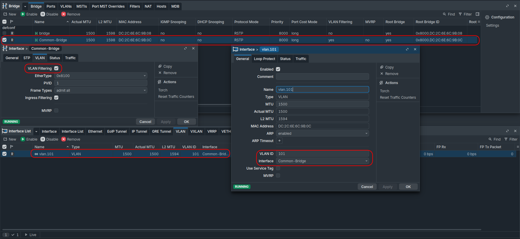
1. Bridge Configuration
Create a dedicated bridge (“Common-Bridge”) to manage the uplink traffic flow.
Code example:
/interface bridge

add name=Common-Bridge vlan-filtering=yes

# Define the VLAN

/interface vlan

add interface=Common-Bridge name=vlan.101 vlan-id=101
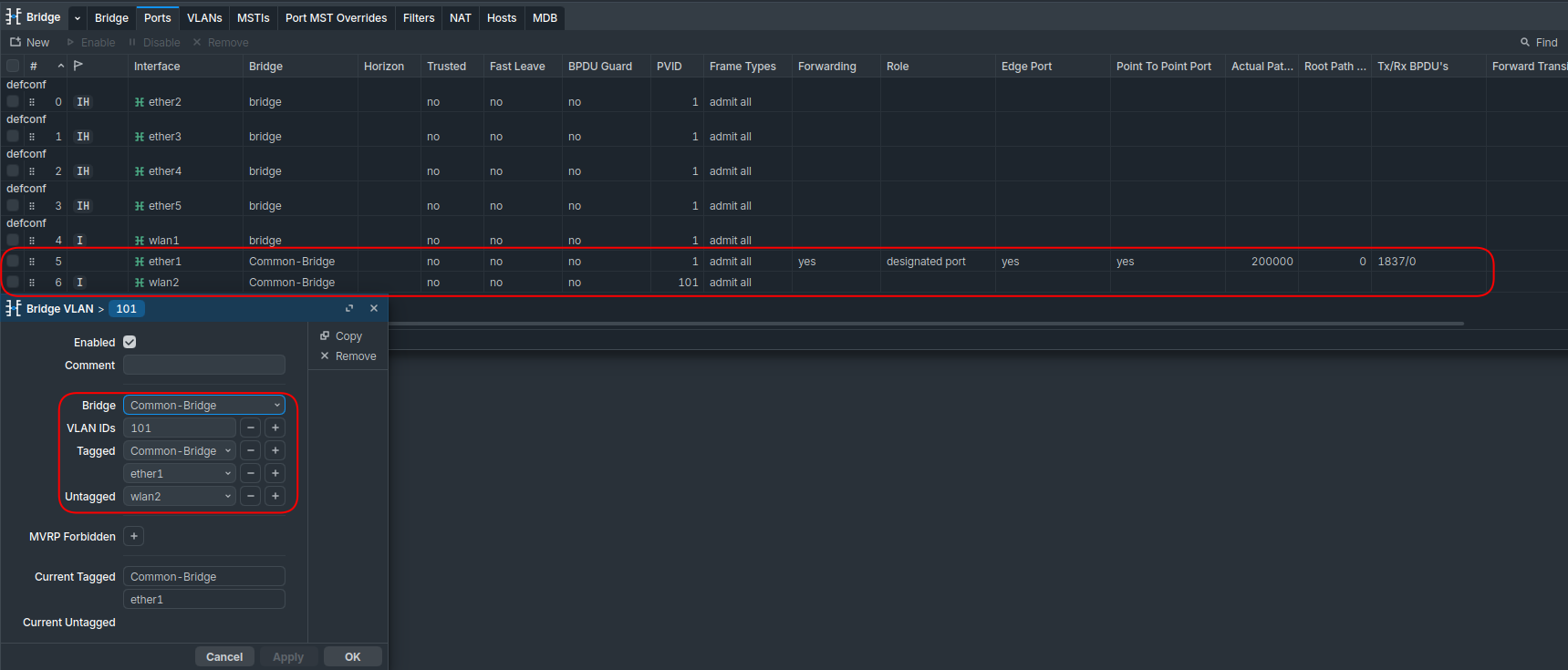
2. Interface Assignment (Ports)
Here we define how traffic enters and leaves the bridge.
Code example:
/interface bridge port

# Add the uplink (Trunk)

add bridge=Common-Bridge interface=ether1

# Add the Guest/Hotspot WiFi (Access Port)

add bridge=Common-Bridge interface=wlan2 pvid=101
3. VLAN Filtering Rules
Configure the bridge to tag traffic leaving ether1 and untag traffic leaving wlan2.
Code example:
/interface bridge vlan

add bridge=Common-Bridge tagged=Common-Bridge,ether1 untagged=wlan2 vlan-ids=101
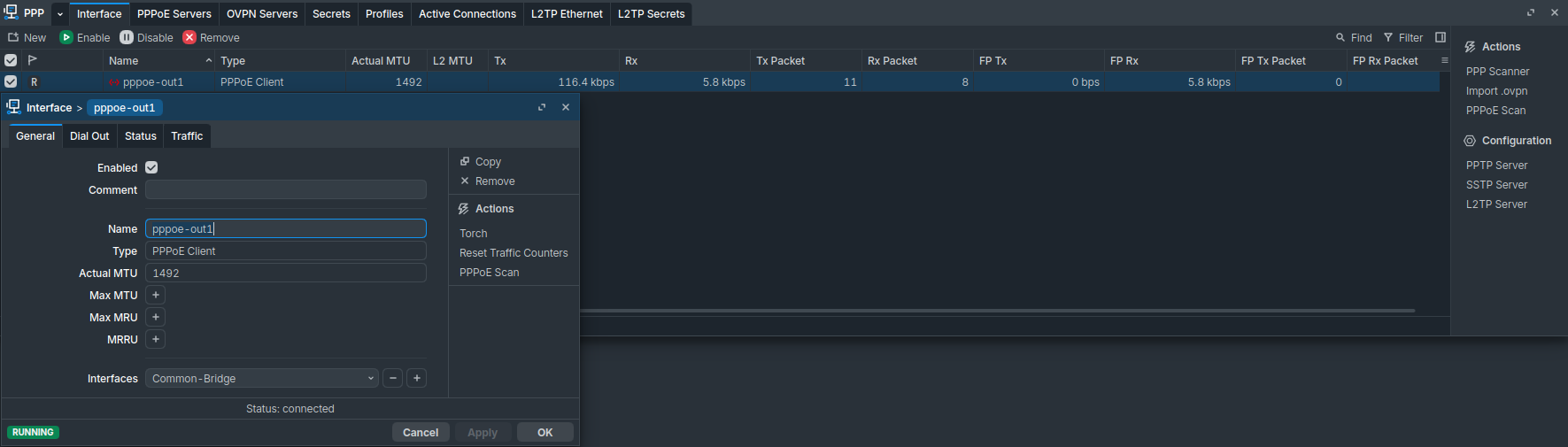
4. PPPoE Client Setup
The PPPoE client runs on the Common-Bridge interface. Since no PVID was specified for the bridge interface itself, it operates on the default VLAN (untagged/native), allowing it to discover the Splynx PPPoE server on the NAS.
/interface pppoe-client

add add-default-route=yes disabled=no interface=Common-Bridge name=pppoe-out1 \

user=YOUR_SPLYNX_USER password=YOUR_PASSWORD
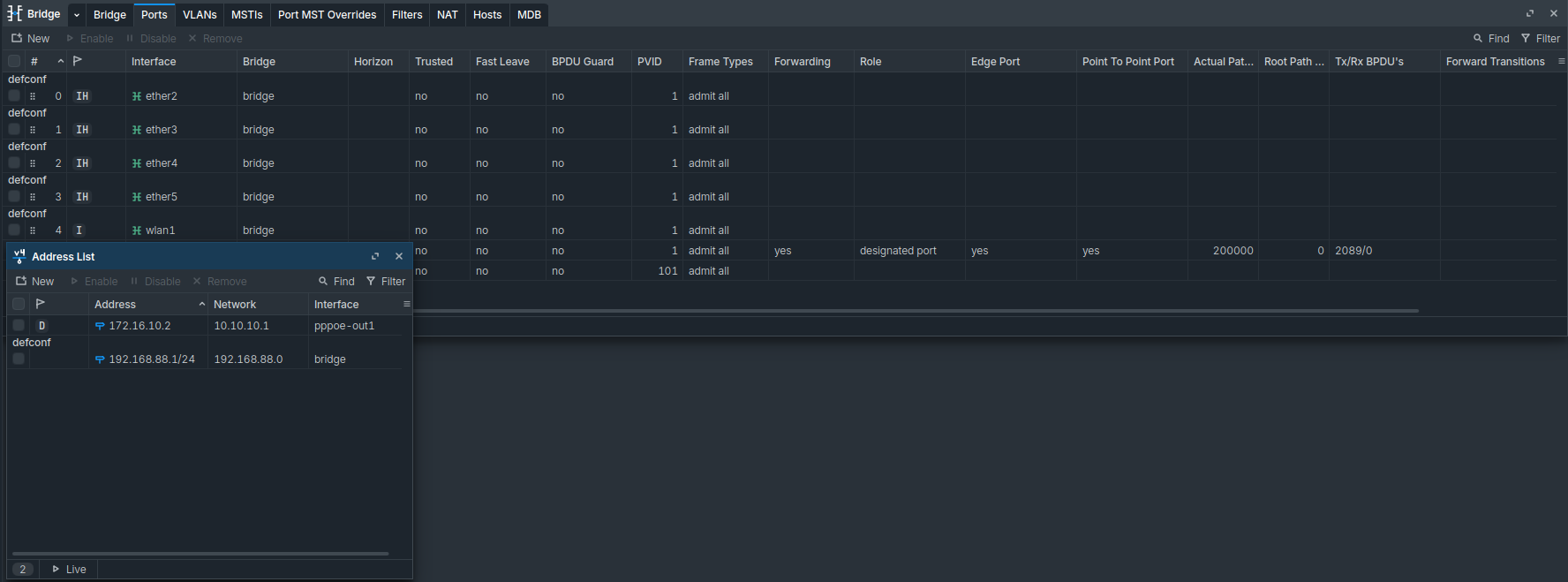
5. LAN Side (Standard Home Network)
Standard configuration for the customer’s private devices (using bridge and wlan1).
Code example:
/interface bridge

add name=bridge

/interface bridge port

add bridge=bridge interface=ether2

add bridge=bridge interface=ether3

add bridge=bridge interface=ether4

add bridge=bridge interface=ether5

add bridge=bridge interface=wlan1

/ip address

add address=192.168.88.1/24 interface=bridge network=192.168.88.0

/ip dhcp-server

add address-pool=default-dhcp interface=bridge name=defconf
Part 3: Operational Logic & Fallback Scenarios
This topology allows for dynamic service switching based on the interface the user connects to, or the state of the network.
Scenario A: Simultaneous Use
-
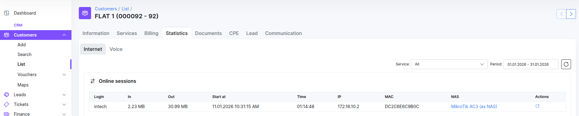
Private User: Connects to wlan1 (Private Bridge). Traffic is routed via pppoe-out1. Internet access is controlled by Splynx.
-
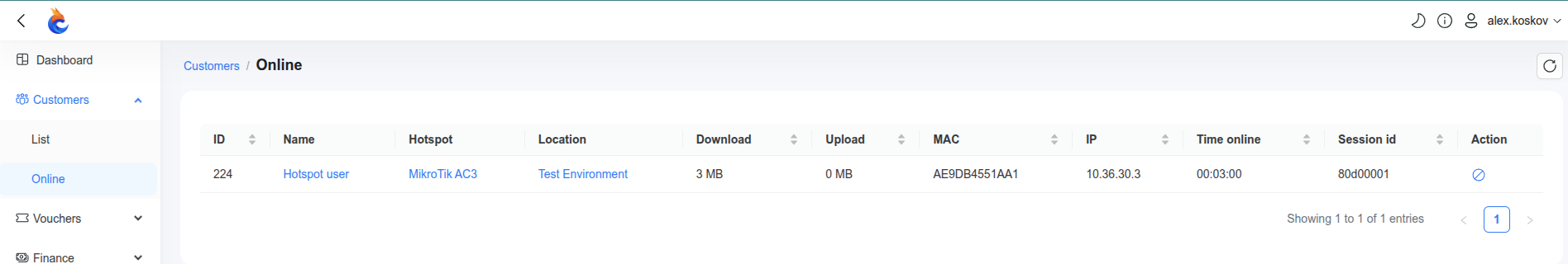
Hotspot User: Connects to wlan2. Traffic is tagged VLAN 101, sent to NAS, and intercepted by the Powerlynx Hotspot.
Scenario B: Automated Failover (Scripting)
You can implement a script (via Netwatch or Scheduler) on the CPE to automatically direct users to the Hotspot if the PPPoE subscription expires or the connection fails.
Logic:
-
Monitor pppoe-out1 status.
-
If PPPoE is Down: Enable wlan2 (or move wlan1 to Common-Bridge with PVID 101). The user is redirected to the Powerlynx portal (e.g., to pay a bill or log in as a guest).
-
If PPPoE is Up: Disable wlan2 or restore wlan1 to the private bridge.
Netwatch script example:
down

:local interface "pppoe-out1"

:log warning "No PPPoE-connection. $interface unavailable. Enabling Hotspot..."

:foreach port in=[/interface/bridge/port find interface=wlan2] do={

/interface/bridge/port enable $port

}

:if ([/interface/wireless/get wlan2 disabled] = true) do={

/interface/wireless/enable wlan2

:log info "Hotspot (wlan2) has been enabled"

}

up

:local interface "pppoe-out1"

:log warning "PPPoE-connection $interface is UP. Disabling Hotspot..."

:foreach wlan in=[/interface/bridge/port find interface=wlan2] do={

/interface/bridge/port disable $wlan

}

/interface/wireless/disable wlan2
This ensures that even when the primary ISP connection is down, the device maintains L2 connectivity to the provider’s management network (Hotspot/VLAN 101).